



PCB Shielding Can Stainless Steel EMI RF Shield Cover
Category:
Key Words:
Product parameters
Parameter | Specification |
Product Name | EMI Shielding Can / RF Shielding Cover / PCB Shielding Can |
Material | Stainless Steel (SUS304 / SUS301), Nickel Silver, Copper |
Thickness | 0.05 mm – 0.30 mm |
Manufacturing Process | Chemical Etching + Stamping + Bending |
Surface Treatment | Tin Plating / Nickel Plating / Gold Plating / Natural Finish |
Shielding Effectiveness | 30 dB – 90 dB (depending on design & frequency) |
Frequency Range | MHz – GHz |
Dimensional Tolerance | ±0.01 – ±0.03 mm |
Flatness | ≤ 0.05 mm |
Hole Size | ≥ 0.03 mm (etching dependent) |
Structure Type | One-piece / Two-piece (Frame + Cover) / Clip Type |
Mounting Method | SMT Soldering / Through-hole / Clip-on |
Edge Condition | Burr-free (etching process) |
Operating Temperature | -40°C to 300°C (depending on material) |
Corrosion Resistance | High (optional plating for enhanced protection) |
Application Level | PCB Level / Module Level Shielding |
Customization | Size / Thickness / Hole Pattern / Structure / Surface Treatment |
Standards | RoHS / REACH compliant |
Product Description
Product Introduction:
This PCB shielding can is a precision EMI shielding can manufactured from stainless steel for high durability and stable shielding performance. The RF shielding can is designed to protect sensitive components from electromagnetic interference, ensuring reliable signal transmission. This stainless steel can is suitable for high-density electronic layouts.
Applications:
PCB protection, communication modules, automotive electronics, industrial control boards, signal-sensitive devices
Solving the Heat vs. Shielding Dilemma: A Guide to Ventilation Design
In the design of modern electronics, engineers often face a conflicting challenge: Heat Dissipation and Electromagnetic Interference (EMI) shielding.
High-performance components like CPUs and RF modules generate significant heat and require maximum airflow to prevent overheating. Conversely, a PCB Shielding Can acts as a Faraday cage, theoretically requiring a solid, sealed metal enclosure to contain electromagnetic waves.
If you seal the box, the components overheat. If you open the box to let air in, you risk signal leakage.
So, how do you balance these opposing forces? The answer lies in intelligent Ventilation Pattern design and precision manufacturing.
The Physics of Shielding: It's About Wavelength, Not Area
A common misconception is that the total surface area of the holes determines shielding effectiveness (SE). In reality, the shielding efficiency is dictated by the maximum linear dimension of the aperture relative to the wavelength ( λ ) of the interfering signal.
To maintain high SE, the longest dimension of any opening (hole length or diameter) must be significantly smaller than the wavelength of the highest frequency you are trying to block.
This is where Micro Perforation technology becomes essential. By utilizing smaller holes, we can increase the total open area (porosity) for better airflow without compromising the electromagnetic seal.
Hole Geometry: Choosing the Right Pattern
The shape of the ventilation hole plays a critical role in both airflow efficiency and shielding performance.
1. Round Holes (Circular Apertures)
Round holes are the industry standard for Stainless Steel EMI RF Shield Covers.
- Advantage: They offer the best structural integrity and the lowest perimeter-to-area ratio, which minimizes diffraction.
- Application: Ideal for general-purpose shielding where uniform airflow is needed.
2. Square or Rectangular Slots
- Advantage: These can be oriented to direct airflow in specific directions.
- Constraint: The "length" of the slot is the critical factor. A long slot acts as a slot antenna, leaking high-frequency signals. If you must use slots, they should be short or broken up into smaller segments.
3. Honeycomb (Hexagonal) Patterns
- Advantage: This is the most efficient packing geometry. It provides the maximum open area for airflow with the minimum amount of metal obstruction.
- Performance: Honeycomb patterns often provide a higher strength-to-weight ratio, making the RF Shield Cover more rigid.
The "Micro" Advantage: Why 0.1mm Matters
To achieve high Heat Dissipation without sacrificing SE, the goal is to pack as many holes as possible into the shield's surface.
Traditional stamping processes struggle with "micro" holes. Punching tiny holes (e.g., < 0.5mm) into thin stainless steel can cause tool breakage, burr formation, and material deformation.
Our factory utilizes advanced chemical etching to overcome these limitations. We can achieve a minimum aperture of 0.1mm.
Why is 0.1mm capability a game-changer?
- Higher Porosity: You can fit thousands of 0.1mm holes in the same space as a few large 1mm holes. This drastically increases the total open area, allowing hot air to escape efficiently.
- High-Frequency Shielding: Smaller holes can block much higher frequencies. A 0.1mm aperture provides excellent shielding效能 even for GHz-range signals (like 5G or WiFi), whereas larger holes would allow leakage.
- Burr-Free: At 0.1mm scale, a burr could completely block the hole. Our etching process ensures these micro-holes are clean and open.
Design Guidelines for Optimal Performance
When designing your PCB Shielding Can, consider these rules of thumb to balance thermal and EMC requirements:
- Prioritize Hole Density: Instead of a few large holes, opt for a dense array of Micro Perforation holes. This maximizes airflow while keeping the maximum aperture dimension small.
- Avoid Long Slots: If using a slot pattern, ensure the length of the slot is less than 1/20th of the wavelength of the noise frequency.
- Consider Material Thickness: The depth of the hole (material thickness) also affects shielding. Thicker materials with small holes act as waveguides, which can further attenuate signals.
- Placement Matters: Place ventilation holes away from the most sensitive high-frequency traces on the PCB to minimize the risk of coupling.
Conclusion
You do not have to choose between a cool-running device and a compliant EMC test result. By leveraging high-density micro-perforation and selecting the right hole geometry, you can achieve both.
Our chemical etching capabilities allow us to create complex Ventilation Patterns that are impossible with traditional stamping, ensuring your Stainless Steel EMI RF Shield Cover performs perfectly in both thermal and electromagnetic environments.
Need Help Optimizing Your Shield Design?
If you are struggling to balance thermal management with EMC compliance, our engineering team is here to help. We specialize in high-precision PCB Shielding Cans with complex micro-venting.
Contact us
to discuss your specific thermal and shielding requirements.
- Contact Person: Luna
- WhatsApp: 12132219094
Questions and Answers
Frequently Asked Questions (FAQ)
Q1: How does hole size affect shielding effectiveness (SE)?
The rule of thumb is that the maximum linear dimension of the hole should be less than 1/20th of the wavelength ( λ ) of the highest frequency you wish to block. Smaller holes (Micro Perforation) allow for higher SE at higher frequencies.
Q2: Which hole pattern offers the best airflow?
A hexagonal (honeycomb) pattern typically offers the highest open area percentage (porosity) for a given hole size, providing superior Heat Dissipation while maintaining structural rigidity.
Q3: Can you manufacture ventilation holes smaller than 0.2mm?
Yes. Our chemical etching process allows us to produce holes as small as 0.1mm. This is significantly smaller than what is typically achievable with mechanical punching, allowing for finer mesh patterns and better high-frequency shielding.
Q4: Do I need to worry about burrs in small ventilation holes?
Yes, burrs can block micro-holes and cause short circuits. However, our etching process is inherently burr-free, ensuring that even 0.1mm apertures remain completely open and clean.
Factory Description
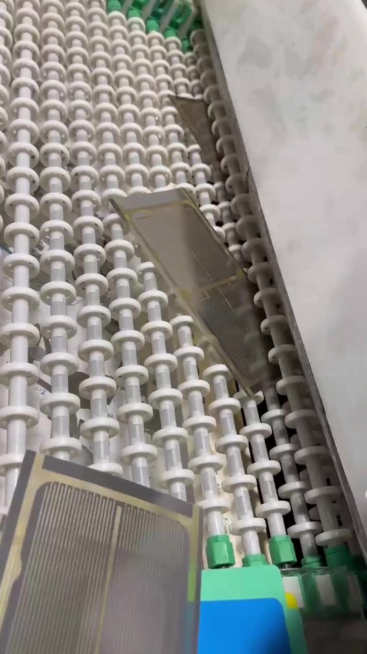
We have a full set of etching production equipment and mature processing technology. We can manufacture products in any shape with mesh sizes as small as 0.1mm, according to your requirements.



Our Advantage
Factory Direct Shipping
Our products undergo 100% QC checks before shipment, and we ensure compliance with international standards. If you require specific certifications for your target market, just let us know, and we'll meet those requirements.
Experienced Design and Manufacturing Team
We work closely with customers from the design phase to help avoid potential product flaws, ensuring both the functionality and design meet expectations.
Excellent Supply Chain Management
We can quickly adjust production schedules to meet your urgent deadlines, whether it's for large bulk orders or smaller rush orders.
OEM & ODM Support
We offer the option to print your logo or other customizations.
Strict Quality Control
Our products undergo 100% QC checks before shipment, and we ensure compliance with international standards. If you require specific certifications for your target market, just let us know, and we'll meet those requirements.
Certificate
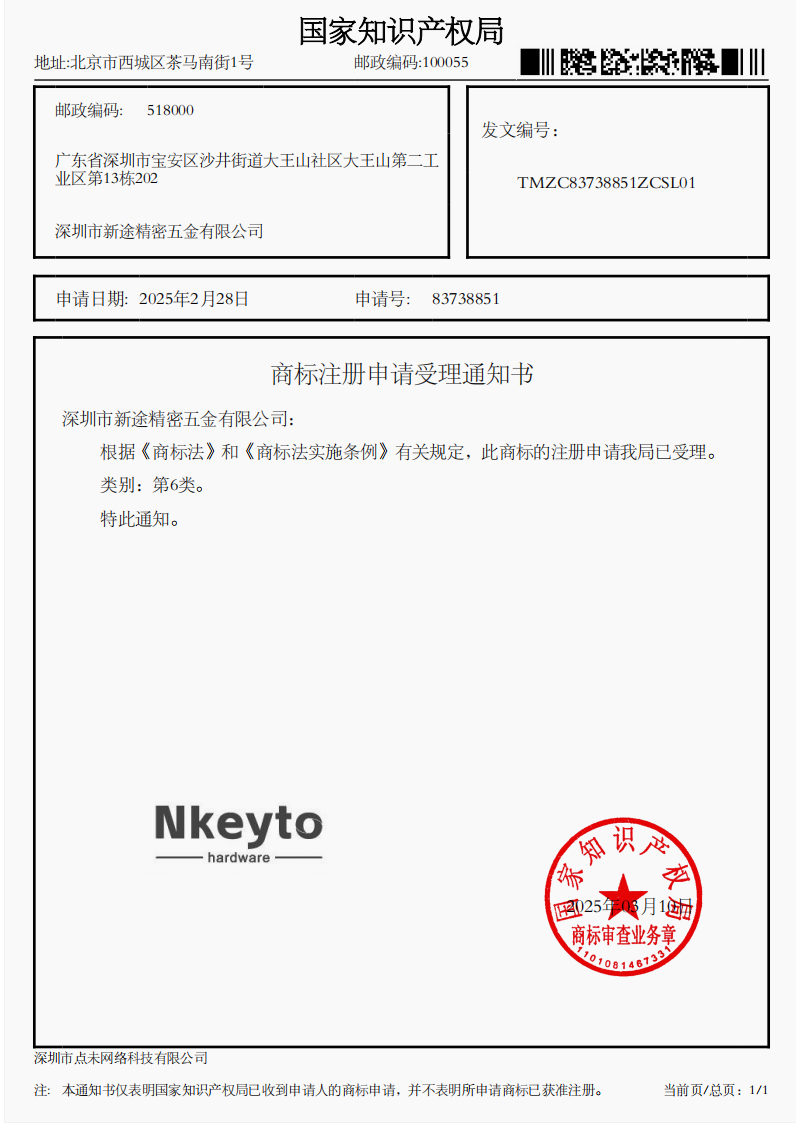
商标6类

9001
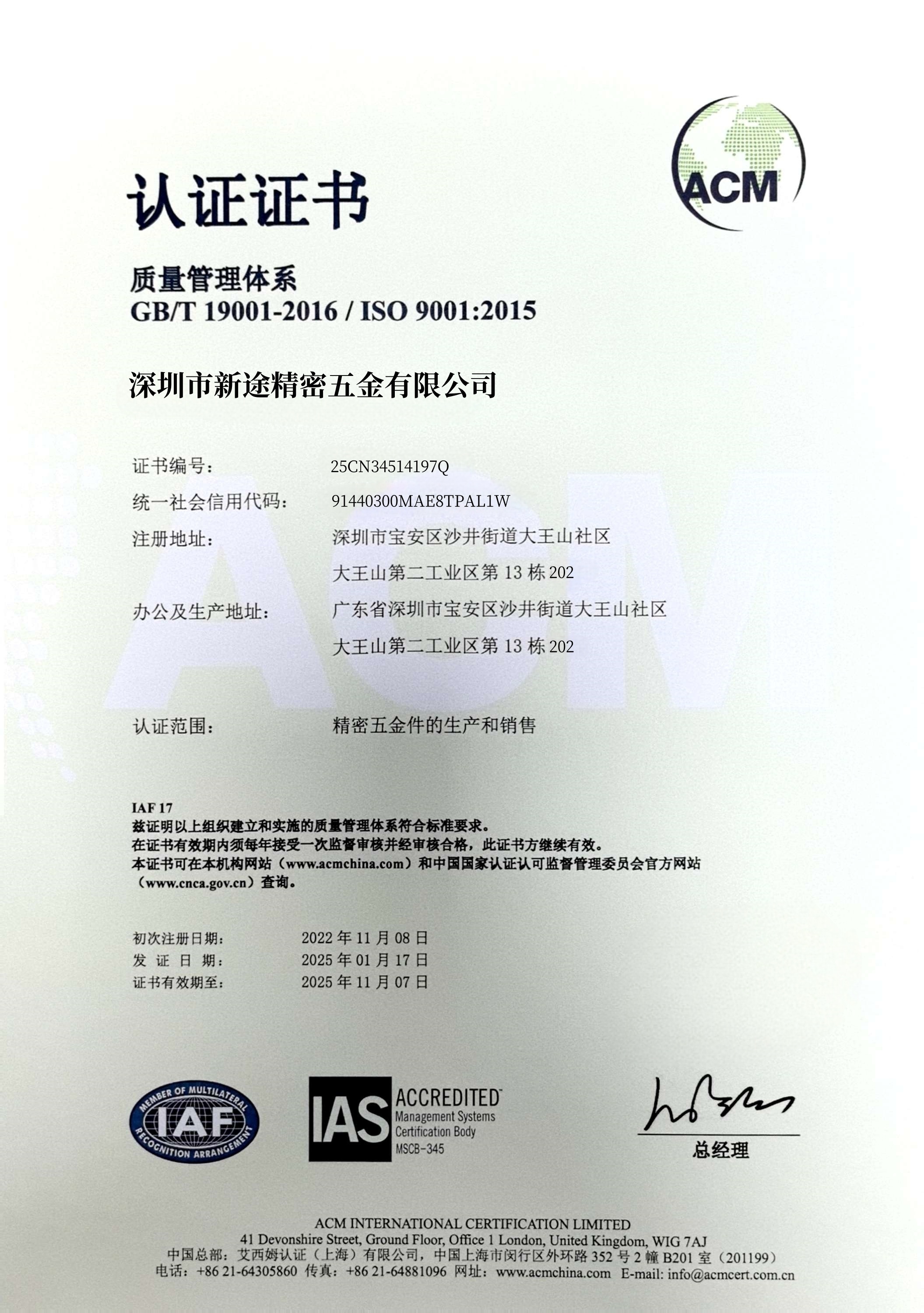
质量认证


Related Products

Shenzhen Nkeyto Precision Hardware Co., Ltd. is a factory specializing in precision hardware processing, committed to providing customers with high-quality products and services.We look forward to working with you.
Contact Us

E-mail: luna@nkeyto.com

Tel: +1 213-221-9094

Add: 13th Building, 202, Dawangshan Second Industrial Zone, Dawangshan Community, Shajing Street, Bao'an District, Shenzhen, Guangdong Province
Powered by: CEglobal
Copryright © 2025 Shenzhen Xintu Precision Hardware Co., Ltd.




Back To Top