



Ultra-thin Stainless Steel Stiffener Plate for FPC & Consumer Electronics
Category:
Key Words:
Product parameters
Parameter | Description |
Material | Stainless Steel (SUS304, SUS301, SUS430, etc.) |
Thickness | 0.05mm - 2.0mm (Customizable based on customer requirements) |
Dimensions | Custom sizes, maximum size: 500mm x 500mm; common sizes: 50mm x 50mm, 100mm x 100mm |
Processing Methods | - Chemical Etching - Laser Cutting - CNC Machining - Precision Stamping |
Surface Treatment | - No Oxidation - Electroplating - Passivation - Polishing |
Hole Precision | ±0.05mm (Higher precision available upon request) |
Edge Processing | - Deburring - Edge Grinding |
Tensile Strength | ≥ 500 MPa |
Applicable Industries | Mobile Phones, Consumer Electronics, Automotive Electronics, Medical Devices, Wearable Devices, Industrial Control |
Customization Service | Full customization according to customer drawings or designs |
Lead Time | - Small batch: 5-7 working days - Large batch: 15-30 working days (depending on complexity) |
Quality Control | - Strict quality inspection for each batch - Full inspection for dimensions, surface quality, and processing precision before shipment |
Packaging | Anti-static bags/plastic bags packaging, with carton box for outer protection to prevent damage during transportation |
Product Description
Design Guide: Key Considerations for Custom Flexible PCB Stiffeners
Designing a Flexible Printed Circuit (FPC) is a complex balancing act between flexibility and rigidity. The stiffener is the component that tips the scale, providing the necessary support for connectors and components. However, a poorly designed stiffener can lead to assembly failures, circuit damage, or manufacturing delays.
For engineers and PCB designers, understanding the fundamental rules of stiffener design is essential. Whether you are using chemical etching or laser cutting, certain design principles apply to ensure your custom stiffener is not only manufacturable but also reliable in the field.
In this guide, we outline the critical design considerations you need to know before sending your files to production.
1. Clearance and Avoidance: The "Keep-Out" Zone
One of the most common issues we see in stiffener design is insufficient clearance. A stiffener is rarely just a solid rectangle; it often needs to accommodate components, solder joints, or test points on the FPC.
The Golden Rule:
Always provide adequate clearance (avoidance) between the stiffener edge and any raised features on the PCB.
- Component Avoidance: If a component (like a resistor or IC) sits on the same side as the stiffener, the stiffener must have a cutout (window) that is larger than the component itself. We recommend a minimum clearance of 0.3mm to 0.5mm on all sides to account for assembly tolerances.
- Solder Joint Protection: For connector areas, ensure the stiffener does not interfere with the soldering process. The stiffener should support the gold fingers but leave the actual soldering pads accessible.
- Via Clearance: If your FPC has vias (holes) in the reinforcement area, the stiffener must have corresponding apertures. A common mistake is sizing the hole exactly the same as the via. Always add a tolerance buffer (typically +0.1mm to +0.2mm to the diameter) to prevent the stiffener from covering the via pad.
2. Stress Management: The Power of Rounded Corners
Sharp corners are the enemy of mechanical reliability. In a stiffener, sharp internal corners act as stress concentrators. When the FPC is flexed, or if the stiffener is subjected to impact, cracks are most likely to initiate at these sharp points.
Design for Durability:
- Fillet and Radii: Always use rounded corners (fillets) for internal cutouts and the outer profile of the stiffener. A radius of R0.2mm or greater is generally recommended for chemical etching.
- Tear Stops: For long, narrow slots, adding a small circular "tear stop" at the ends of the slot can significantly reduce the risk of the metal tearing during handling or assembly.
- Bend Radius: If you are designing a stiffener for a dynamic flex area (though generally discouraged), the design must accommodate the bend radius. However, most stiffeners are for static support. Ensure the stiffener edge is at least 1mm to 2mm away from the dynamic bending zone of the FPC to prevent the rigid edge from digging into the flexible circuit during movement.
3. File Requirements and DFM Feedback
To ensure the highest precision, the format of your design data matters. While we can work with various formats, some are far superior for manufacturing.
Preferred Formats:
- DXF / DWG: These are the gold standard for 2D metal fabrication. They provide precise vector data for our laser cutters and etching phototools.
- Gerber: While primarily for PCBs, Gerber files (specifically the mechanical layer) are also acceptable. However, ensure the scale is 1:1.
The Value of DFM (Design for Manufacturability):
Even the best engineers can miss a manufacturing constraint. Before you send your files to production, ask yourself:
- Is the hole too small for the material thickness?
- Is the bridge between two holes too thin, risking breakage?
At our factory, we provide a free DFM review for every project. If your design has a 0.1mm bridge that is too fragile for 0.1mm thick steel, we will flag it and suggest a modification before we start production. This proactive communication saves time and prevents costly errors.
Quick Design Checklist
Feature | Recommendation | Reason |
|---|---|---|
Inner Corners | Radius (R) > 0.2mm | Reduces stress concentration, prevents tearing |
Via Clearance | Pad Size + 0.2mm | Ensures the stiffener doesn't cover the pad |
Component Clearance | > 0.5mm | Accounts for assembly tolerance |
Edge Distance | > 0.2mm from circuit edge | Prevents short circuits and edge damage |
Conclusion
A well-designed stiffener is invisible in its operation but critical to the device's function. By paying attention to clearance, stress relief, and file accuracy, you can ensure your FPC assembly is robust and reliable.
Need a Design Review?
Don't let a small design error delay your project. If you are unsure about your clearances or material choice, our engineering team is here to help. We offer free DFM analysis to ensure your stiffener design is optimized for manufacturing. Contact Luna on WhatsApp at 12132219094 to discuss your design or upload your files for a quote.
Questions and Answers
Frequently Asked Questions (FAQ)
Q: Can I design a stiffener with sharp 90-degree corners?
A: While possible, it is not recommended. Sharp corners create stress points that can lead to cracks in the metal or tearing of the FPC. We strongly advise using rounded corners (fillets) for all internal and external angles.
Q: What is the minimum "bridge" width (the metal between two holes)?
A: Generally, the bridge width should be at least equal to the material thickness. For example, if you are using 0.1mm thick steel, the bridge should be at least 0.1mm wide. However, for better strength, we recommend a bridge width of 0.2mm or more.
Q: Do I need to indicate the adhesive thickness in my drawing?
A: Yes. If you require adhesive (PSA), please specify the thickness (e.g., 0.025mm or 0.05mm) in your drawing or notes. This helps us calculate the final "Z-height" of the assembly to ensure it fits your connector.
Q: Can you help me if I only have a physical sample and no digital file?
A: Yes. If you have a sample, we can perform 2D scanning to reverse-engineer the design and create a DXF file for you. We can then send you the drawing for approval before production begins.
Factory Description
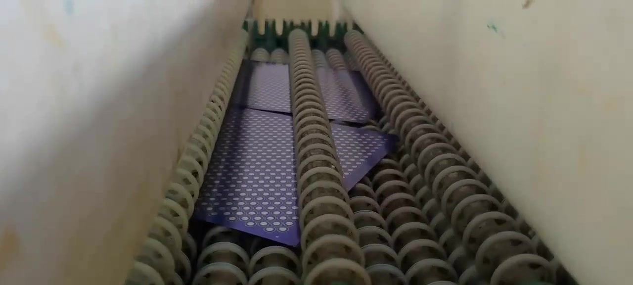
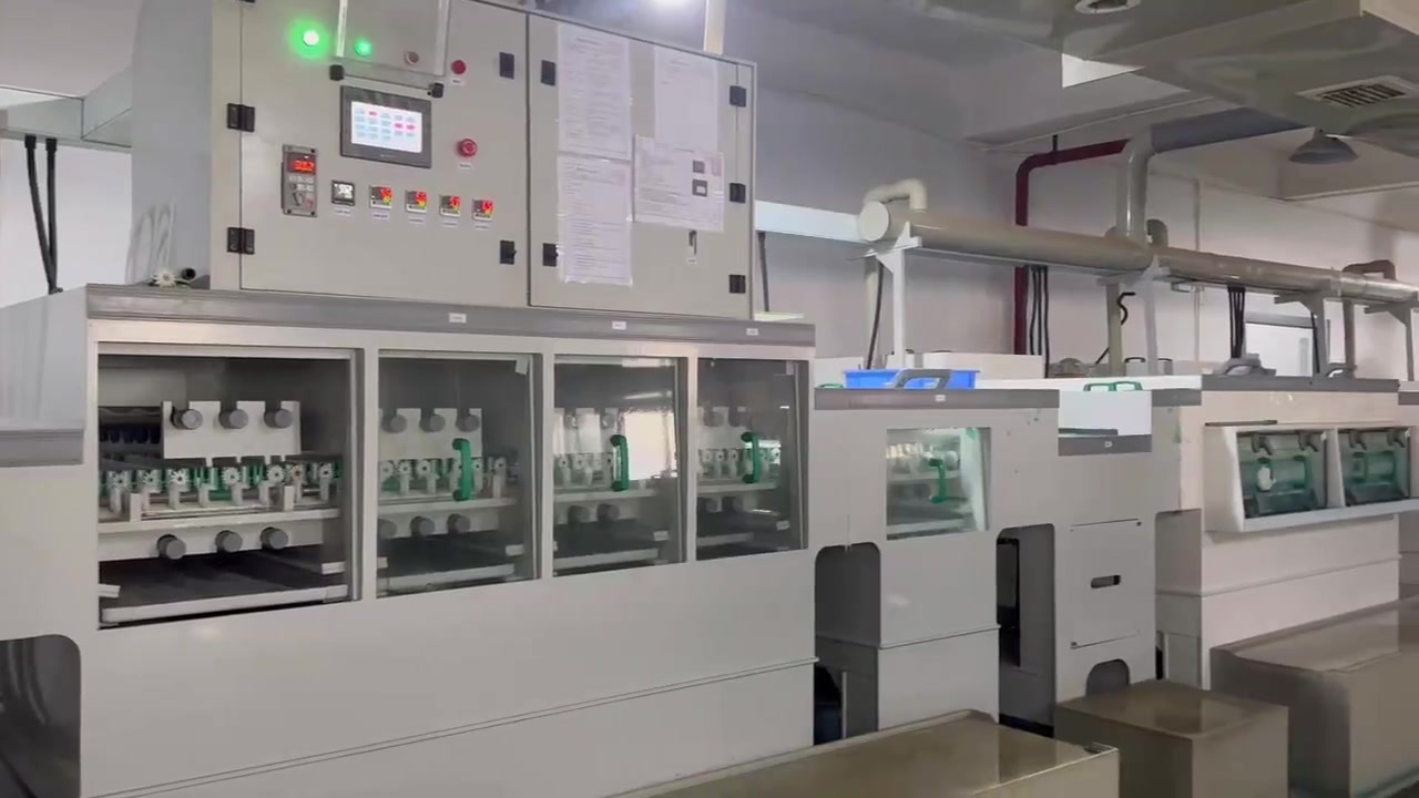
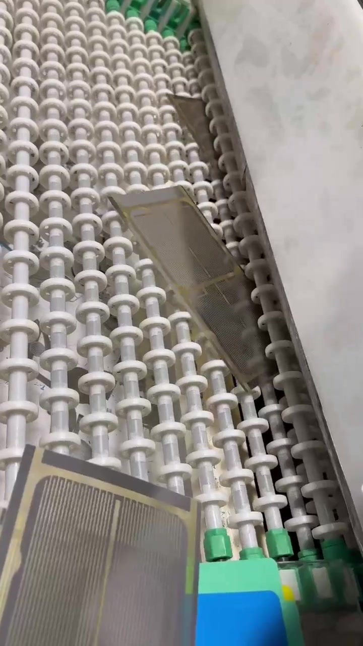
We have a full set of etching production equipment and mature processing technology. We can manufacture products in any shape with mesh sizes as small as 0.1mm, according to your requirements.

Our Advantage
Factory Direct Shipping
Our products undergo 100% QC checks before shipment, and we ensure compliance with international standards. If you require specific certifications for your target market, just let us know, and we'll meet those requirements.
Experienced Design and Manufacturing Team
We work closely with customers from the design phase to help avoid potential product flaws, ensuring both the functionality and design meet expectations.
Excellent Supply Chain Management
We can quickly adjust production schedules to meet your urgent deadlines, whether it's for large bulk orders or smaller rush orders.
OEM & ODM Support
We offer the option to print your logo or other customizations.
Strict Quality Control
Our products undergo 100% QC checks before shipment, and we ensure compliance with international standards. If you require specific certifications for your target market, just let us know, and we'll meet those requirements.
Certificate
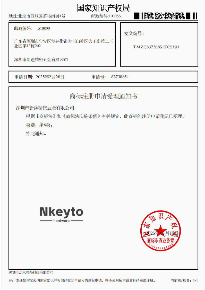
商标6类

9001
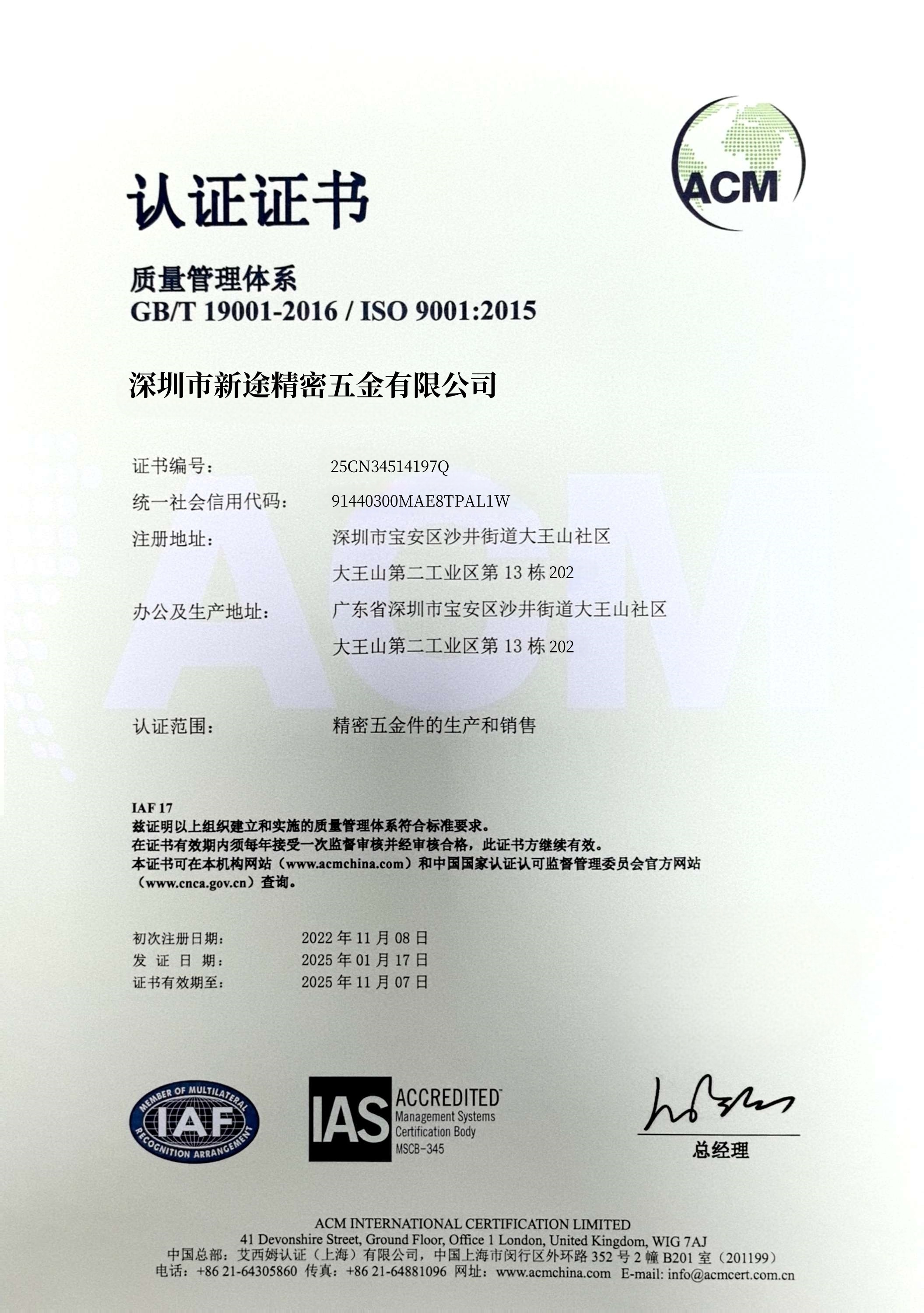
质量认证


Related Products

Shenzhen Nkeyto Precision Hardware Co., Ltd. is a factory specializing in precision hardware processing, committed to providing customers with high-quality products and services.We look forward to working with you.
Contact Us

E-mail: luna@nkeyto.com

Tel: +1 213-221-9094

Add: 13th Building, 202, Dawangshan Second Industrial Zone, Dawangshan Community, Shajing Street, Bao'an District, Shenzhen, Guangdong Province
Powered by: CEglobal
Copryright © 2025 Shenzhen Xintu Precision Hardware Co., Ltd.




Back To Top